Wednesday 13 January 2010

That's what I call Playing to the Gallery

Here then, are the results.

24kg of Mig welding wire
9,200 litres of shielding gas
9 electric drills
6 angle grinders
12lbs of lead
5l Glacier white

A stack of used grinder discs over 2ft high.


We got there in the end, everything just turned out fine. These photos were taken before I finished the new sunroof. Oh well.


Here then, is ANU333L.


And possibly the only example of a BGT with peaked, composite rear wing tops?


Now she is done, she will be kept in the garage and only taken out on dry days.

Or not. She is protected well enough to withstand a good ragging, which is what she gets. Hard use, with thorough and careful maintenance will cause no problems. What is the point in owning the thing and not using it?


She will do.


Tuesday 12 January 2010

Deft Needlework

It had always been very tatty, but I thought I’d leave it be until it was too bad to go on. It needed tidying up every time it was closed, and was a bit of a pain. Then on the way to meet on the ledge with Richard at Cwmorthin in the summer, the Webasto sunroof let go on the M4 and started flapping about annoyingly. The vinyl tore and at certain speeds made a very loud noise which was a tad irritating. It was much better when closed, as the loose torn parts could be tucked in, however, I very rarely have the roof closed. Eventually while touring in the Lake District, the braided tensioning wires tore through the stitching down each side of the roof, and flapped around with the loose vinyl, wrecking the still-soft paint on the C posts as they bashed against it.

Enough was enough, and I set to making a new roof. A length of correct fabric-backed vinyl of the correct type, thickness and pattern was bought from Woolies trim, along with some high strength adhesive and a curved upholstery needle. I sourced some rot-proofed black sailmaking thread, and set to making the roof for a few days over Christmas when I was drinking and not using the car.

The old roof was disassembled, and the headlining repaired. The locking mechanism was also repaired and overhauled, then the vinyl was removed from the frame, and stretched out to form a template. The pictures show the rest.


Nailing it around the Lake District, sadly quite often with the roof closed and needing constat tweaking and tucking in. At every photo stop. Bahh, that's not impressive.


First step- a big piece of cloth-backed vinyl. The outline and features of the old roof was chalked on, and with a lot of courage the new roof was cut out with dressmaking scissors.


The rear rail positioned correctly, new tensioning wires routed down each side. This showed where the vinyl had to be sewn together to make a length of piping to hold the tensioning wire. I used PVC-coated electrical cable, instead of the wire rope used originally, this had a habit of cutting through the stitching allowing the roof to fall apart. The front and rear frames were cleaned up, and the sharp edges at the front were sheathed in the outer insulation of mains electrical cable. This gave a softer, rounded edge to wrap the fabric around, so it would be less likely to wear through.


Scary 2" curved needle, and a cunning stitching technique learnt from me mother (thanks mum)


At the front, the front rail is put in place and the tensioning wires looped through the U-bends. It can just be seen that the sunroof fabric has had an exra layer glue to the underside in all the places there is a lot of load on it. Where it is folded over the edges of the frame, the double-thickness should make it stronger, less prone to wearing through and tearing.


The vinyl is then glued onto the front and rear rails, and pegged in place with lots of pegs. LOTS of pegs! At each corner, the vinyl was folded over itself several times to produce a smooth curve around the frame, hopefully this will be less prone to falling apart than cutting slits in it to allow it to be curved.


The finished roof, with the frame and repaired headlining in place. Will it fit though?


Oh yes! It works, smooth as you like. And fits a treat, and looks like the original did when new.


And it shuts, locks and seals perfectly. Note the stitched piping should be flush with the roof to give a seal, but it is slightly higher at the moment. In about a year, the vinyl will have reached its full stretch, and the tensioning wires can be tucked under the transverse frames, rather than alongside them, giving the correct chape to the finished roof. Better too tight for a while, than have the vinyl stretch and give a loose-fitting roof.

What a complete and utter mess

Test runs were conducted up and down the drive, all 30 feet of it. The aim was to floor it up the slope, and try and hit 15mph going into the garage before jamming on the brakes to avoid clobbering me Mum’s deep freezer. That was a rather limiting source of entertainment, so I took her down the road to the MOT place, and things were not fun. The delightful bloke came in after five minutes and told me she had failed. Apparently she needed a door or wing mirror on the nearside, and after I pointed out the correct place in his rule book, he realised he was wrong and went back out there in a huff. She was going to have an offside mirror anyway, I had not had time to fit it yet as it was not necessary for road legalness.

He eventually failed her on an insecure brake pipe which was actually secure, I returned for the free retest with the cable tie done up two clicks further and she was passed. Hurrah!  He then decided to be friendly, and told me he liked my new brake pipes but I should put coppergrease on them to stop them rusting. I hadn’t the heart to tell him they were quite clearly made of copper, and therefore rather unlikely to corrode…..!


One of the early test drives to Wellow, in Somerset, to drive through this big ford. The water level was a bit low sadly.... I did most of the test driving at night, to avoid embarassment of the the unfinished Valleri.
The rest of the car was hastily put together, and she was taken on longer and longer drives, although there were very few problems really. Then it dawned on me I had to go up to the Lake District to see Richard for some touring, then down to Lancashire to see Calum, for some touring. And there was still a lot to do…

I did my best, but I still ended up setting off up North with no chrome trim strips on the doors, I did the front and rear wing strips but then I had to set off. These eventually got done in Richard’s garage the third day I was there. Oh how fantastic to be driving her again, but rather annoying that so much had not been done, like fitting the remaining two driving lamps, wiring in them and the reversing lamps, finishing the headlining and many other little jobs. But I finished her on time… sort of!


Valleri and Meg together at last amongst the Western fells. Yes, there's certainly something missing, oh and the other two driving lamps as well!

Meet on the Ledge! Valleri and Weelet somewhere around the Lancashire and Yorkshire border. You can just about see the sunroof starting to fall apart too.... bahhh.

Just some little finishing touches to do now.....

My MGB GT She's a runner now...

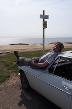
All that was left to do was reassemble the entire car, from every single component. And quickly, too. Summer had arrived long ago, and I would soon be leaving for University, leaving the car at home of course. I did very much want to get her done, and use her for a bit, after all this work. The YGC road trip had taken place, which I should have been on, and I had to catch a lift to Fairport Convention’s Cropredy festival with Richard and Meg, due to not quite having the car done on time. I was working flat out though, all day and every day, I had been working at weekends up until now to fund the project but now needed time more than ever. So it was out in the garage until the early hours (and sometimes not so early, working until 3am many nights) to get her back in one piece.

Sadly, there was no time even to photograph the reassembly. I have a few photos of bits and bobs, then my photos jump straight to the car on the road and done. A bit of a shame. BUT- there isn’t much point in writing a lot about the reassembly. The bodywork was the unusual and interesting part of this restoration, anyone can strip and reassemble an MGB, it isn’t exactly difficult. So I will only give brief details, and note where things were done differently from usual.
The first stage was to get everything in place so the engine could be fired up. Then, if the engine worked, the next stage would be making the car ready for an MOT. Then at least it could be run in and tested, while everything else was put back on. Onwards!

The clutch master cylinder was bolted to the pedal box, then the new brake master cylinder. This was an old stock metal reservoir Lockheed job. I eventually managed to find a good one, after buying several and finding the bores corroded in all of them. This one was in the original packaging, and still had the original protective oil in the bore, which once removed was absolutely perfect. There are very, very few metal master cylinders left in good nick, so I was glad to have found one. The plastic bodied cylinders are hideous. Don’t you hate pathetic legislation. I wish someone would get the metal type back in production, claiming they are an alternative high capacity clutch master cylinder or such. Then everyone could fit them in their braking system, and the retailers would make a small fortune selling them, even at a reasonable price.

Anyway I had my brake master cylinder, which got new seals, along with the clutch master cylinder. I was going to try out silicon brake fluid, seeing as almost the entire brake and clutch hydraulics had been replaced. The higher boiling point, no damage to paintwork and no need for frequent replacement was a bonus, the main reason to use silicon was for its non-hygroscopic nature. Having found one of the last good brake master cylinders with a nice bore, hopefully the silicon fluid will prevent it from corroding. The pedal box was then bolted to the bulkhead which I had built from scratch in that area, it fitted beautifully. The banjo unions which connect to the back of the cylinders would be bolted up from behind, through the hole in the bulkhead. Why the Haynes resto manual states this cannot be done is beyond me. Did they really fail to realise that the huge rubber plug you remove from the hole behind the master cylinders is to allow you to tighten the unions easily from inside the car? Duhh!

The wiring loom was next. I had sorted this out during the summer evenings back in the paint stripping days. The rear loom was a bodged mess or random wires and a conduit box, so this was binned. The main loom was thoroughly cleaned, checked over and any areas of loom tape that were chaffed or damaged were repaired. Heatshrink tubing and more layers of tape were added over the vulnerable areas of the loom where it passed through or rubbed against metal. All the connections were thoroughly cleaned, and I went through and soldered every single connector on the loom. I do not trust crimped connections on a car. They are a major cause of electrical faults and failures. Soldering is the only way to make a lasting joint, in a harsh environment with strain and vibration. All spade connectors were tightened slightly with pliers, so they would grip the male connector more firmly, and a dab of Vaseline added to keep the dirt and moisture out. All the double connectors for bullet terminals were treated in the same way. All terminals on switches, gauges etc were thoroughly cleaned for good contact. So it was put into place, and retained where necessary. All wiring loom P-clips, brake, clutch and fuel line and hose clips were of the rubber-lined sort, to ensure there was no metal-on-metal contact.

A new rear wiring loom was around £45, I decided to make my own because it would be slightly cheaper, and also because I wanted to. Borrowing the one of Nigel’s car to use as a template, I ordered the correct gauge wire from Autosparks, along with the correct terminals, heat shrink tubing, insulation tape and proper non-adhesive vinyl loom tape. I used tent pegs in the lawn as a former, and made a copy of Nigel’s loom, which ended up looking identical. Later I planned to make an auxiliary loom, to run the extra rallying electrics, relays, instruments, switches and lamps.

The dashboard was due to be fitted, and it was in a bit of a state. The old crackle-black paint was removed, and the reverse side painted gloss black. I decided to have a go at repainting the front in crackle black, despite the issues many people have had. The key is heat. Thankfully it happened to be a very hot, sunny day, so the dash was left in the sun to warm up. A heat gun was borrowed, and played over the dash to try and bring the heat up evenly. Once hot enough, doing about half the dash at a time, the wrinkle finish paint was sprayed on, the heat was continually played over it. The head causes just the right depth and type of wrinkles, but it is a difficult balance. The whole area has to kept hot evenly, and at the right temperature too. It is a narrow band, too cold and the wrinkles will not form, too hot and they will become huge, and the paint will bubble and burn. Overall it worked, I was relatively happy with it and to do a better job I think a temperature-controlled furnace would be required, which I don’t really have.
With the dashboard in place, the steering column was added, and aligned accurately with the steering rack, to take the loads of the bearings in the rack. The resultant steering movement was light and easy, no problems there.

The dash looked very bare, so it was decorated with the new crash rail I had bought, as the vinyl was torn and the wood had rotted in the old one. The dash top vinyl was removed from the decayed biscuit board, and glued over some suitable thin board. Instrument and switch time, the switches had all been serviced and cleaned, and were plugged into the loom and put into the dashboard. The instruments were added, and I made up new retaining plates for the speedometer, as the only place which seemed to sell them, that daft parts company called Moss, wanted the usual extortionate price of £9 for two bent pieces of steel. Rear light clusters were added, the heater was plugged in and so was the wiper motor.

People who have known this car for a while will remember the dodgy 12v battery installation under the boot floor. Having a single 12v to my mind is a good plan, the modern 6v batteries cost a lot and last a couple of years at the most. Just not worth wasting the money. I decided to put the battery in the offside battery cage, to free up boot space. It would also leave room in the nearside cage for a box to be made to store spares. I just about managed to get the battery into the cage, it is an 075 which is enormous. Once you have the hang of it though, it can be got in and out without getting any scars. It’s a very tight fit but worth it. The cranking power and duration from this size of battery is incredible, very handy when you are young. If you decide you want to stay overnight at a lasses house, you just need to kick out the wire to the fuel pump, then sit there on her drive cranking the engine over and over for minutes at a time. Sorry, car’s obviously broken, can’t get home and it’s freezing cold. Ha ha.

I wired in various ingenious electrical systems to help prevent little pikeys thieving the car. The battery was restrained in its cage, and the positive and negative cables run to the correct places. Ignition on…. Wa-hey! No smoke. And all the things that were plugged in worked! Heater, wipers, rear lights… we’re getting somewhere now.

Time to dress up the engine with all its ancillaries. The new water pump went on, the correct rocker cover, the new uprated alternator, the pushrod cover and crankcase breather and the starter motor.


Late evening sun on the engine bay.... coming together nicely now, with old parts and new. The piece of paper on the manifold side engine mount was there to remind me to connect up the earth strap before attempting to turn the engine over, to prevent fried accelerator and choke cables!


And from the other side, note the earth strap has now been bolted on! The polished and laquered inlet manifold with its core plug brackets is fitted, along with the exhaust manifold and downpipe. The heat reistant silver looks a bit daft, but will disappear in a few months anyway.


My garage is a strange, surreal place, like my mind. You have to expect the unexpected, like a hedgehog coming in then getting stuck under the fridge.


Awww! The hedgehog, after extracting it from under the fridge. It also got into the offside floorpan, daft thing.


Next came the fitting up of the exhaust. Not just any exhaust. The other defining feature! Along with those peaked rear wings…. The prototype cherrybomb exhaust system.

I was told that the particular exhaust system under Valleri was the first ever to use a cherrybomb centre box, developed to give more ground clearance to the car and the prototype to the MGOC club sports exhausts, and it was thought to be made in the 1980s. It certainly is different to any other exhaust system I have seen, and could well be the predecessor to the modern centre cherrybomb system, rather than using a smaller rear box to enhance the sound, this was welded in place of the standard centrebox to avoid grounding out on speed bumps. The system is the standard bore, with a cherrybomb in the middle which is barely wider than the rest of the pipework. The pipe bends upwards before joining to the hefty straight through rear box, protecting it from damage by rocks or other projections. The tailpipe is standard bore and fairly long, going almost to the rearmost point of the rear over riders.

And Holy Mong does it sound good. Not like anything else, not even remotely like modern cherrybomb centre systems. The idle is hollow and rough sounding, much like a vintage tractor, in fact this is one of the things which drew me to the car in the first place. Accelerating she growls, and I mean a real growl, not a crappy monotonous droning like fuel injection gives, not even the usual sweet MGB growl, but far more aggressive and tuneful, amplifying the full beauty of the exhaust note carburettors give. Then when you get to 1950 revs up to about 2100rpm, it becomes a snarl. I’ve never heard any other car sound quite like it, people have likened it to a Chieftain tank, and a radial engined aircraft pulling out of a dive. Utterly fantastic, trust me. The finer details of the snarl vary with temperature and humidity, it varies slightly in volume, pitch and hollowness, and one occasion the sound waves actually flapped my clothing. It is rather loud through that rev band, and can clearly be heard from over 3 miles away on a still night. Over 2100 revs it goes back to a growl and becomes progressively quieter, to the point that in Overdrive at 60mph there is nothing but a little bit of wind noise, and quiet conversation is easy, even without any soundproofing whatsoever.What more could you ask for?


A piece of history, this exhaust system! Sounds unbelieveable too.

The radiator was carefully flushed, repainted and put into place with new hoses, and the cooling side of things were done. I then rebuilt the distributor, it was found that although the centrifugal advance plates were fine, the weights were worn, so a scrap distributor from a Series III Land Rover wielded new parts to keep the timing happy. No crappy electronic ignition here, of the sort favoured by old people. A well maintained distributor (And I mean well maintained, you can’t have a piece of tosh and then call it a piece of tosh, or maintain it badly then call it unreliable) is far superior to a computer thing under your bonnet. What do you do when that fails for no apparent reason, like they do? You’re stuck at the side of the road. If you do not have the time and skill to look after a set of points, why have a classic car? What can go wrong with a mechanical distributor… the points can fail, and the condensor can fail, both of which can be replaced at the roadside in five minutes, and cost a few pounds each at most. Having said that, at Beaulieu I bought another distributor for £1, rebuilt that too, fitted new points, condensor, cap and leads, replaced the earthing wires inside and timed it to the car before pinching up the locking plate. Now, if there is any ignition problem whatsoever, I can remove the whole thing at the roadside with two bolts, and put the spare ignition system on. It cost less than £10 too.

Fuel time, and the copper pipe was run from the tank to the boot, and the other pipe from the boot to the bulkhead. Finally I could pit the grommets and straps along the underside of the car to retain the wiring loom, positive cable, fuel line and brake line. Then one of the double ended SU pumps was fitted into the boot, wired then plumbed in. The intake manifold was fitted with metal angle brackets, bolted into place by the large threaded plugs at either end of the manifold. The angle down and rest against the core plugs, which were Loctited in place and have a mechanical fixing too, ensuring they cannot come out which would obviously destroy the vacuum in the inlet manifold.

The lovely twin SU HS4s, which I had rebuilt on getting the car home after buying it, went back on. No braided fuel hose in sight though, the modern reproduction stuff is all that is available, and the rubber perishes very quickly, but of course you cannot tell due to the braiding. High quality black fuel tubing is far cheaper and safer, so that was used. The Filter King pressure regulator was mounted on the flat part of the bulkhead via a home made aluminium bracket.


Mmm all clean and fresh.. The inny manni core plug retaining brackets can be seen, and the newly sprayed rocker cover.
With the loud pedal and choke cable connected up, and the engine filled with oil, there were fewer and fewer excuses left. The fuel pump was filling the float chambers, everything was looking good. The coil was disconnected and the engine spun over on the starter and oil pressure built up. A bit of choke, I turned the key and the engine turned. It did not fire, so I tried again with a bit more choke and nothing happened. Getting out and shuffling sadly to the engine bay, I realised that the coil was still connected. Durrrrrr. She fired up instantly and settled down to her old rorty growl running fast with the choke out. As the temperature came up, she would then idle perfectly, just as before with that smooth unevenness only Valli has. The carburettors and not been adjusted since they were removed from the engine at the start of the restoration, and did not need adjusting. She was running, charging and would shortly be moving, once the brakes and clutch hydraulics were finished.


All well in the engine bay. I do like that engine, the emo red was perfect in the spray gun as well, so I sprayed the rocker cover. Look at those reflections!


Everything necessary to legally drive the car on the road was then fitted, so I could get her an MOT and start to run her in and iron out any problems while finishing her off. The front wings went on, then the doors, and here I learnt how to paint cars properly. Which, in future, will be done with the doors and wings already finished, so when fitting the doors I do not ruin the paint on them and the wings. I resprayed the damaged areas, sadly the paint was a slightly different colour, so I am going to have do another smaller respray in the near future to get everything right. It was unfortunate as the paint turned out rather well, a beautiful gloss, and I am going to have to do all that polishing again. Ah well, at least I know now.

Thursday 3 December 2009

Up and over

A new Borg and Beck clutch kit had arrived in a red, black and white cardboard box, containing at least 40% recycled fibres, and labelled Borg and Beck, 1 clutch kit MG MGB 4cyl. Well, I have to include some obvious and irrelevant detail to pad it out a bit, don’t I?

I have bought a clutch alignment tool, which made getting the pressure plate central very easy. The clutch casing was bolted to the flywheel, and a new release bearing clipped into place in the gearbox. The release bearing arm had been fitted with a new bronze bearing, and the bolt on which it pivots was replaced to ensure slop-free de-clutching. Hurrah! A new gaitor was fitted to the release bearing arm to stop water getting in, and the split pin in the drainage/breather hole in the bottom of the bellhousing was removed. I was going to put some flexible tubing through the hole, and extend this up inside the car, to stop water getting in when fording. The same will be done to the rear axle breather, so it can breathe air rather than water.

The first motion shaft splines were carefully greased with the AP clutch parts lubricant, as well as the release bearing pivots. Then the gearbox was sneaked towards the engine, and shoved on the back. Bolted up, the drive train was ready to go in!


New friction plate on the flywheel, with the alignment tool.


Mmm a new carbon release bearing. I had heard a few stories of newly fitted release bearings breaking up after a very short time, so either there are substandard parts out there, (very likely), or idiots have been buying “New old stock” perishable parts off the internet. A fanbelt that has sat around for 30-40 years? Erm they degrade with time as well as use, so do cooling hoses…. Ah well, there are plenty of idiots out there, who sadly managed to buy a classic car. Why buy a release bearing which could have sat in the damp for 30 years, then fit it to your car, knowing it is a major job to remove the engine and gearbox to access the clutch? Anyway I bought new, and genuine Borg and beck, so things shouldn’t go wrong.


And there we have it. Most of the engine, minus the fragile bits. The rebuilt gearbox, and overdrive. The rocker cover is a spare, while the proper one is being painted, and the sump was removed and painted once the engine was in the car. A stupid thing to do really, but there was a reason for it, which I cannot remember. Time to put it in then...
Engine, gearbox and overdrive all in as one was to be the way. Either that, or the box and overdrive then the engine, however it was easier fitting them together first. This would involve a silly angle to get the assembly in, as it is rather long with the overdrive and all, and the B series is extremely high. Oh well, just get on with it.

Sheets and general padding were draped over the panelwork in an attempt to avoid damage in a collision with the engine. A hefty tow rope was deemed enough to take the weight, and taking it slowly and carefully, it all just about worked.


Valleri waiting expectantly. The engine is supported by the green strap, with hefy rope as a backup as I was not keen on dropping it.The rope could also be adjusted to gain the silly angle required to get the whole lot in. The front wing splash guards can be seen in the background, hung up to dry (They had been there since painting the underside!)


Ha-harr! Victory!

Back down from the stupid angle, getting closer to being in... note the protection, thankfully it was not needed and nothing got bumped.


And there we have it. How beautiful. It fitted perfectly, and looks rather nice against the white and black paint.


Mmmmm! There is still a lot of car to put back together though!
Once the engine was in, it was bolted to the mountings at the front. Perfect fit! Underneath, the gearbox crossmember was ready to go on. This had the bolt holes elongated to allow it to be physically fitted, a major design flaw. New mounting rubbers had been fitted, with some difficulty and sore hands! It was still an awkward job fitting the gearbox crossmember, but once done, she had a power unit and drive train at last.

Continuing the number-based titles... 1,2,3,4 Overdrive!

Time to fiddle with the gearbox. This had been working very well, but there was a lot of play in the first motion shaft bearing, it could be wiggled well over ¼”. So it seemed logical to strip the whole gearbox down for inspection, cleaning and replacement of the dodgy bits.

The first motion shaft bearing housing was removed, along with the selector tower, the overdrive and the rear extension. I spent a bit of time playing, to determine exactly how everything fitted together and worked. Disassembly continued, until the entire thing was in pieces. Despite having not done a great deal of gearbox work before, if enough photos, drawings and notes are taken, things are much easier, gearboxes are very simple really.


Gearbox casing cleaned and scrubbed... The overdrive has been removed, leaving the rear extension and main casing.


Yours Truly. Purpose of this photo- remember to find out what this little bracket does, before reassembly. (it turned out the be the bracket that a clip is bolted onto. The clip holds the overdrive and reversing light switch wiring in place).


The rear extension has been removed now, and the selector rods are being withdrawn.


The big nut allows the third motion shaft to be disassembled. The big, double roller bearing seen here is just about indestructible, and has very little force exerted upon it from any direction.


Removing the bearing from the first motion shaft proved difficult, due to the lack of a ring spanner of the correct size, and a vice not big enough. A hilarious afternoon of going backwards and forwards to Matt’s house then mine ensued, as we attempted to use his man-sized vice, but forgot various vital tools. Eventually, the reverse thread nut was removed, the bearing replaced and the first motion shaft was ready to refit.

The baulk rings were in good condition, however I fitted some with even lower mileage. I also fitted a slightly less mashed reverse gear, not that there was much between them. All other gears were in perfect order. The second motion shaft was in a bad way, with severe damage to the shaft and one of the needle roller bearings. This looked to have been cause by water in the oil, rather than just severe wear, but thankfully I had a spare second motion shaft, and a new needle roller bearing was ordered from Moss. Being Moss, they sent one with a missing needle roller. Brilliant. The one part I was relying on to get the gearbox back together, and they send one with a fairly obvious manufacturing defect. I am glad I only use them for bits I cannot source elsewhere… Thankfully, I managed to find a spare needle roller bearing, and I fitted that.
The second motion shaft had a little bit too much play, and for some unknown reason, the selective thrust washers necessary to take up this play are no longer made. Why? This is a MGB four sync gearbox, common and popular? Oh well, the endfloat required was 2 thou, there was 7 thou, and 5 thou crankshaft thrust washers thankfully fit.

The outside of the gearbox had been cleaned with the paraffin gun before disassembly, and now the inside was cleaned as well. All components were thoroughly cleaned before reassembly, bearings were washed in meths and all was good. The gearbox was put back together with new gaskets, the selector rods refitted with the interlock, and the overdrive was bolted on the back. Botheration.


Ahh, the gearbox has been cleaned and reassembled. it is a thing of utter beauty. The small gears in the bottom right are the reverse gear, behind them is the second motion shaft, up top is the third motion (output) shaft. Mechanical genius and awsomeness, I need to rebuild another as an ornament.


Lovely syncro hubs, first gear is nearest the camera, and fourth is furtherst away.


Don’t you hate that sickening moment as you gently tighten a UNC bolt into alloy, and it suddenly goes all loose? I wasn’t over-tightening it, honest. That meant that the overdrive had to come off again, the rear extension on the gearbox had the corroseponding hole drilled out to take a ½” bolt rather than a 7/16”, and the overdrive had to be drilled and tapped to take a ½” bolt cut down in length.

At the same time, the overdrive valves were disassembled to check no tapping swarf had got inside, and all was in condition. The overdrive then went back on, and all was well.

One Three Four Two

Ho-kay. Time for some clean, precision work on a big lump of cast iron which when assembled correctly, should be torquey, long of stroke and fantastic in the exhaust note department. B Series engines are as simple as they get, this was the third time I was taking one apart so there were no major challenges.

Having very little money, and not much time now either, no machining work was to be carried out. The engine is in good condition and the bores, crank and cam bearings were only slightly worn, so there was potential for many miles left without spending a fortune. A full strip down and reassembly replacing all the expendable items was therefore sensible.

Eventually, I would like to get the block relinered, line bored, get the crankshaft straightened, reground, have the liners bored and fit new pistons, get the whole lot dynamically balanced, add new camshaft bearings and get 3-angle valve seats cut. When I can afford it. Mild tuning will also take place, that does not compromise her usability on the road. So a mild road cam, and a cylinder head which I will port for torque rather than higher revs, with bulleted manganese bronze valve guides, but probably fitting 1.56” inlet valves to keep the torque where I want it.

The block was stripped and parts were inspected. New bits were ordered, meanwhile the paint was removed from the outside of the box and the inside was thoroughly cleaned with a paraffin gun, which was very effective at removing oil and sediment and re-depositing it over the stupid modern car which the father insists on driving. The oilways seemed clear enough so I decided against removing the brass gallery plugs, there was no build up of sediments . The waterways were poked with long pointy objects until there were no limescale deposits left. This is obviously a major cause of engine overheating, causing uneven cooling and blocking the passage of the cooling water through the block. The final step in the cleaning process was giving the block a thorough cleaning with a lot of water and soap and washing powder. This works well as long as all surfaces are kept wet at all times, and the whole thing is dried as quickly as possible then soaked all over with rust preventative, or in the cast of the exterior of the block, the first coat of paint was brushed on as quickly as possible.

In the absence of a pressure water, a stiff bristled hose brush was used to supply water and scrub away dirt. Lots of soap, a lot of water and cleaning every nook and cranny in the block, paying particular attention to the webbing and reinforcements where the dirt had accumulated and was difficult to dislodge. I was extremely pedantic about cleaning the engine parts and maintaining all was sterile, out of necessity. The worst engine wear happens after a rebuild when specks of dirt wreck the new bearings within seconds. All the oilways and waterways were flushed out thoroughly, and I was only happy when I could run a clean tissue anywhere inside the block and have it remain spotless.

WD40 a-plenty on the inside, the engine was moved into the early summer sun to dry quickly, with more WD40 as it dried out. This was done very carefully as it is incredible how quickly corrosion will kick in, and it’s already happening long before the naked eye can see it.
Time to get some paint on the outside of the block to stop that rusting, too. Finest BMC Emo red was brushed on, 4 coats in all and it dried lovely and glossy. Yes, I know that black is correct for the 18Vs, but with a red engine it is far easier to see oil leaks at night, so red it was. I also love the colour.

The new main bearings and thrust washers were fitted, the crankshaft added and the main bearing caps torqued up one at a time.


One exceedingly clean block, with the first coat of paint done, and the new main bearing shells and thrust washers fitted.


The crank endfloat was fine, and there was only slight resistance to rotation at each stage. Perfect. The pistons and old rings were re-used, they had plenty of life left in them for now. New big end bearings of course, everything still turned over smoothly.


The crankshaft and camshaft in place, awaiting the pistons and connecting rods, and the oil pump. This photo gives a false impression of how carefully the engine was rebuilt, keeping it spotless inside.


As the engine appears to have been rebuilt for hillclimbing, then rebuilt again for use on the road, is consisted of a strange mixture of parts. The nicest being duplex timing gears in good condition, and these, with a new timing chain, tensioner and camshaft thrust plate, were fitted one the camshaft was inserted. The cam was timed and was near enough spot on, on the nearest tooth, verified using a dial gauge. A new oil pump was fitted, this had a little bit of porting carried out, and all sharp edges were removed. The distributor drive was inserted, the sump fitted and that was the bottom end done.

In the meantime, the cylinder head was being tackled. The waterways were carefully being cleaned, to prevent the head overheating and cracking. The ports were thoroughly cleaned out with an air die grinder, then the valves and seats were ground.


Grinding the valves, whilst on the phone to Richard. Good times.


New stem oil seals, and the valves were fitted. The rocker assembly was practically unworn, so that went back on, and the same went for the pushrods which went back in the block. A nice Payen head gasket was fitted between the thoroughly cleaned mating surfaces, and the head lowered onto the new head studs.


Valves in place, and a top quality head gasket from Payen. Resin impregnated, and with an extra line of sealent to cope with the dodgy seal which can sometimes occur along the ignition side of the engine. The chap around the corner from me who used to rally a late 60s GT told me of the times he used to go for long distance motorway blasts, and lost a fair bit of coolant water out the ignition side of the gasket!
Torqued up, the timing cover was fitted, and the engine was ready to go in as soon as the gearbox was done. I decided to spray the tappet chest cover and crankcase breather casing emo red, along with the rocker cover, for a smoother finish.

Tuesday 1 December 2009

Got a brand new Salisbury axle!

As my original rear axle had destroyed itself, and the car in the process, I required a new one. Mark gave me a new one. Good on him, I was very grateful and he didn’t want payment, only the halfshafts back for, for racing. Which is why he bought the spare axle in the first place.

Here’s a lesson though…. Never interfere with the differential of a Salisbury axle. All sorts of stuff is involved, way beyond what you are expecting, and to carry out adjustments requires axle stretchers, service tools, collapsible spacers and lots of dial gauge and depth micrometer stuff. So when someone with limited mechanical knowledge comes along, (such as whoever rebuilt my differential last), you can see why there is potential for it to fail. In spectacular style, locking one halfshaft and putting the drive through the other, making the car not the easiest thing to keep between the hedges. And entirely unexpectedly too, there was only acceptable play in the diff, which was checked regularly alond with the propshaft joints whenever greasing of the latter took place.

Anyway, I had my new rear axle with un-messed-up diff. I set about rebuilding the bits of the differential which are rebuildable, after removing the halfshafts to give back to Mark. I gave me halfshafts to whichever Land Rover and Marcos garage that was nearest home (alright, it’s probably the only one in the country) along with new wheel bearings, which they pressed onto the halfshafts for dosh. Next I removed the roll pin then pinion pin from the differential, removed the diff gears and cleaned everything up. All was in good order, the axle looks to be a low mileage unit. So new thrust washers were fitted to the sun and planet wheels, the half shaft bearings were packed with grease, the halfshafts fitted and the whole thing was back in one piece. I did the old trick of putting a slit pin throught the roll pin and opening the ends, to prevent any chance of the roll pin coming out of the pinion pin. Hurrah, a nice diff at last, ready to go back in.


New bearing on te halfshaft, ready to be shoved in. They were wound in using the bearing caps and a couple of long bolts, until they were in far enough for the proper securing bolts to be used.


The rear axle was painted in Tetrosyl with all the other black parts. Having been thoroughly cleaned up inside and carefully inspected, the new thrust wahers were fitted, which can be seen here as they are so thick, compared to the old ones which are always wafer thin.


At this point Matt reappeared from University, and was promptly recruited for helping my get the thing finished. So began days of working hard on the car, stopping for pizza and chips, then returning to the car for the rest of the day, and getting a lot done quickly, too. And he managed to put up with my bad moods as things did not fit, were the wrong type, or vital bolts and fittings frequently disappeared just for fun. Good work Sir.


Again, it's superb to be working from a complete kit of parts, all new, recon or refinished to as new condition. New bump stops were fitted, now they could actually be fitted, the original bmp stop mounts had corroded away and were plated over, I repaced them while repairing the rear chassis rails. Polyurethane suspension bushed went on the back as well, along with uprated dampers. One day, the springs may be uprated or the ride height tweaked, who knows...


Our first task was to get the axle attached to the bodyshell. Onwards with the rear suspension then, the reconditioned uprated dampers had been bolted in place, and the leaf springs had polyurethane front eye bushes fitted. They were then bolted into place at the front, and the struggle began to get them fitted at the back. This is easy once you know how, difficulties arise getting the polybushes wedged into the holes in the chaissis rails, then not coming out when the shackle plate is pushed through. They are in a fairly hard to get to position, so leverage is difficult. The main problem though was having too much paint in the holes in the chassis rails, further reducing the clearance. With this cleaned out, much trial, failure, then eventual success got both springs in place at the back.


Dampers and springs fitted. Note the special white grease for the polyurethane spring pads.


The axle could then be brought beneath the car and raised and pulled one way, then the other to get itsitting on the springs. With he U-bolts, spring plates and polyurethane spring pads fitted, the drop links to the dampers and check straps could be bolted on, and the axle was in place.


Axle on! Droplinks in place... U bolts and spring pads in place, bump stop pedestal on. The only remaining object is the axle check strap.


Despite the brakes not being fitted, the rear wheels went on. The car could now roll… she was on herwheels again!